Digital Exchange Port Configuration Options
This document provides an outline of customer Digital Exchange Port connection options when connecting to the Cyxtera Digital Exchange. This perspective is from the customer equipment.
Interface Encapsulation Type
- Layer 2 interface should be configured as a trunk
- Layer 3 interfaces should be configured with logical/sub-interfaces
Limitations
- At this time, Only Per-VLAN implementation of STP is supported. (Example - Cisco PVST, Juniper VSTP).
- Dual home connectivity to single Layer 2 CE is not supported. Layer 2 CE with LAG is required.
- Both fiber connections must be used for redundant connectivity
- At least one Layer 3 device such as a firewall or router
- A Layer 2 VLAN to act as the Internet VLAN within your cage or rack
SFP Compatibility
| Description | Specification | Supported Cables |
|---|---|---|
| SFP 1g LX optic | 1310 nm up to 10 km | LC Duplex OS2 SMF |
| SFP+ 10g LR optic | 1310 nm up to 10 km | LC Duplex OS2 SMF |
| QSFP 100GBASE LR4 | 1310 nm up to 10 km | LC Duplex OS2 SMF |
Connection options
The following connection options are available for Exchange Ports.
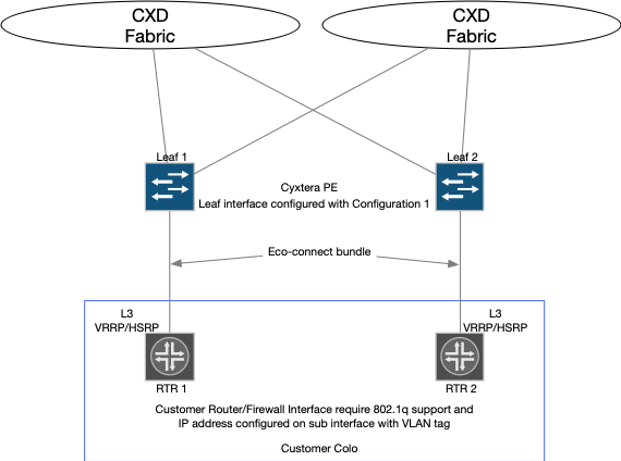
Layer 3 CE
Edge devices that have physical interfaces configured with an IPv4/IPv6 address are considered to be Layer3 customer edge or Layer3 CE. Typically, HSRP/VRRP/GLBP first hop redundancy protocol would be used for failover on the customer router. Only tagged interfaces are supported with this type of customer configuration.
Limitations
- LAG/MLAG is not supported at this time for Layer 3 CE.

Layer 3 CE example
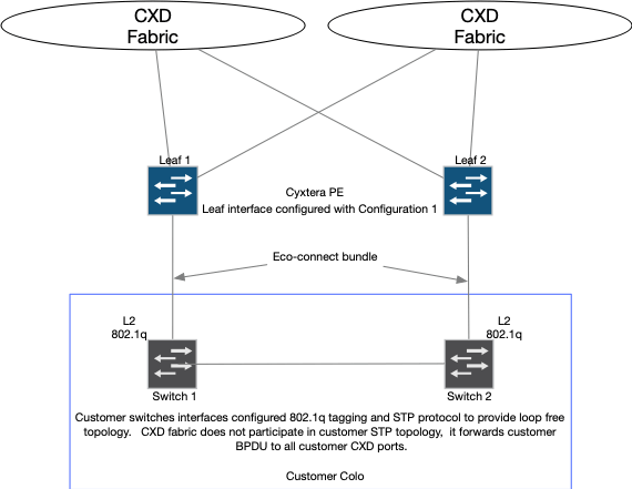
Layer 2 CE
Edge devices that have physical interfaces configured with 802.1q are considered to be Layer 2 customer edge or Layer 2 CE. Customers that use this type of connection typically run STP within their environments to provide loop protection. The Cyxtera digital exchange fabric does not participate in customer STP topology, however, STP BPDU will be passed by the Exchange fabric to all customer Layer 2 CE ports to assure loop free environment through the fabric. This configuration is considered active/standby because of the blocked STP port.
Limitations
- At this time, Only Per-VLAN implementation of STP is supported. (Example - Cisco PVST, Juniper VSTP).
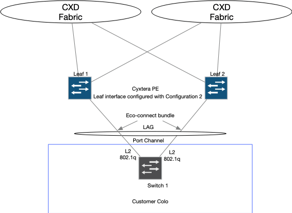
- Dual home connectivity to single Layer 2 CE is not supported. Layer2 CE with LAG is required.

Layer 2 CE example
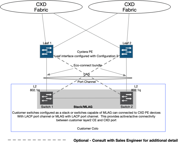
Layer 2 CE with LAG
An additional option for Layer2 CE is LAG/MLAG configuration. This option builds on the standard Layer2 CE configuration. Customers with devices that are ‘stack’ / ‘virtual chassis’ capable or capable of MLAG can be configured to take advantage of forwarding on all links connected to our PE device. LAG/MLAG configuration is considered to be active/active. The Cyxtera digital exchange fabric uses flow-based load balancing for forwarding traffic towards Layer 2 CE ports. An Exchange Port requires LACP protocol for fast convergence of a link or device failure. Exchange port LACP is configured for fast periodic updates. Vendor Proprietary protocols are not supported for LAG/MLAG configuration.
Limitations
- Per Packet load balancing is not supported our PE ports.

Layer 2 MLAG example

Single Homed Layer 2 LAG example
Default Exchange Port Parameters
Customer Interfaces MTU
- Layer 2 - 8964
- Layer 3 – 1500
LACP
- Minimum Link - 1
- LACP – Active
- Periodic – fast
Interface Encapsulation Type
- Layer 2 interface should be configured as a trunk
- Layer 3 interfaces should be configured with logical/sub-interfaces
Troubleshooting
Interface Speed Negotiation
Cyxtera equipment defaults to automatic speed negotiation. For some customer equipment, this is not supported for 1 Gbps connections. In this case, you can force a 1 Gbps speed by editing your Exchange Port and unchecking 'Auto Negotiate.' NOTE: This is not supported on 10 Gbps links.

Auto Negotiate toggle
Physical Port Status
You may view the physical port status of the Cyxtera equipment by selecting your port in the interface. Your ports will show the status of the last refresh time. You can force a refresh by clicking the refresh button.
Layer 2 or Layer 3 connections will show two physical links.
LACP connections will show two physical links and the Aggregated Ethernet Interface status.

LACP connection with all interfaces up.

Layer 2 connection with all interfaces down.
In some cases you may see a stats of '?' or 'Unknown.' This means that the system currently has no information on the port. Please wait 5 minutes and recheck. If the status is still unknown, you may need to open a case with Cyxtera support.
Customer Interface Configuration Examples
The following tabbed section contains sample configuration examples by popular vendors. Customer should consult with their equipment manufacture to provide exact configurations that are compatible with their specific environment.
interface GigabitEthernet0/0/1

 description CYXTERA-EXCHANGE-PORT

 no ip address

 negotiation auto

!

interface GigabitEthernet0/0/1.10

 description IP-Connect-VLAN10

 encapsulation dot1Q 10

 ip address 63.245.12.5 255.255.255.248

 standby 10 ip 63.245.12.4

 standby 10 priority 105

 standby 10 preempt

!

interface GigabitEthernet0/0/1.20

 description IP-Connect-VLAN20

 encapsulation dot1Q 20

 ip address 63.245.13.5 255.255.255.248

 standby 20 ip 63.245.13.4

 standby 20 priority 105
 standby 20 preempt
interface GigabitEthernet1/0/13

switchport trunk allowed vlan 10,90,91,100

switchport mode trunk
ge-0/0/2 {

    description CXD-PORT;

    vlan-tagging;

    unit 10 {

        vlan-id 10;

        family inet {

            address 131.226.200.5/29 {

                vrrp-group 1 {

                    virtual-address 131.226.200.5;

                    priority 255;

                    accept-data;

                }

            }

        }

    }

    unit 20 {

        vlan-id 20;

        family inet {
interfaces ge-0/0/0{

    unit 0 {

        family ethernet-switching {

            interface-mode trunk;

            vlan {

                members [ VLAN_0010 VLAN_0020 ];

            }

        }

    }
}
#Arista Example for Layer2 with MLAG
#Arista DCS-7050QX-32S-R Software image version: 4.18.2
#Port channel configuration on both Arista switches.

interface Port-Channel50

  description port_channel_interface

  mtu 1514

  switchport mode trunk

  mlag 50

Physical interface configuration on both Arista switches.

interface Ethernet4

  description phyical_interface

  mtu 1514

  switchport mode trunk

  channel-group 50

  mode active

#This example does not show supporting mlag and VLAN configurations.
#Layer2 LACP in Access Port Mode

#
interface Ten-GigabitEthernet1/0/14
port access vlan 100
port link-aggregation group 1
#

#
interface Ten-GigabitEthernet2/0/14
port access vlan 100
port link-aggregation group 1
#

#
interface Bridge-Aggregation1
description IP_Connect
port access vlan 100
link-aggregation mode dynamic
#
Updated 8 months ago